Some mechanism covert motion as well as transmitting it.
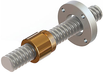
SCREW AND NUT
This mechanism consist of a screw and a nut.The rotatory motion of the nut is converted to a forward linear motion in the screw.
CHARACTERISTICS AND APPLICATIONS
It is a good speed reducer.The screw rotates quikly but the linear motion of the nut is slower.
It is reversible.We can rotate the nut to create linear motions in the screw or rotate the screw to create linear motion in the nut.
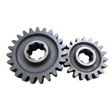
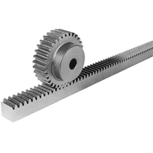
RACK AND PINION
This mechanism consist of a toothed wheel that meshes with a toothed bar.The rotatory motions of the pinion is converted to a linear motion in the rack.
CHARACTERISTICS AND APPLICATIONS
This mechanism is very smooth and precise.
It is reversible.
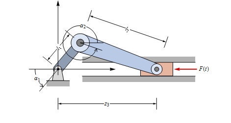
CRANK AND SLIDER
This mechanism consist of a rigid bar that is connected at one end to a crank.
The rotary motions of the crank is converted to reciprocating linear motion in connecting rod.
CHARACTERISTICS AND APPLICATIONS
It is reversible
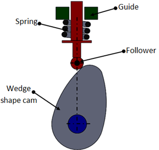
CAMS
Cams are usually elliptical in shape. They are attched to a shaft and, as they rotate, they drive an element called the follower. A spring keeps the follower in permanent contact with the cam.
When the projecting part of the cam hits the follower, the rotary motion of the cam is transmitted by the follower as reciprocating linear motion.
CHARACTERISTICS AND APPLICATIONS
Cams convert rotary motion into linear reciprocating motion.
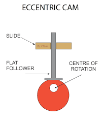
ECCENTRIC CAM
An eccentric is a mechanism similar to a regular acm. It is of a wheel where the axis of rotation isn’t the geometrical centre. It convert rotary motion into linear reciprocating motion and is used in older sewing machines.